A digital counter with N-bits is developed in VHDL in Cadence environment for mixed-signal simulations.

In- outputs
This counter has 3 digital inputs:
- enable (high enable) == counting direction
- reset (high enable) ==put to ‘0’ with LOW
- clock signal
The output:
- an N-bits digital vector (std_logic_vector) with a binary counter
Functionality
The functionality is simple:
After every clock cycle (when the clock rising edge) and while the enable is HIGH, the counter will count one step upwards.
If the enable is LOW, after every clock cycle at the rising edge event, the counter goes one step down.
When the reset is LOW, the counter is set to zero (synchronized reset).
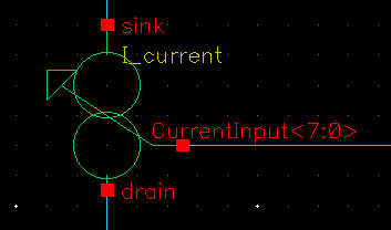
Note that for this counter, (because of the application) the inputs on the symbol were drawn on the right side and the output on the left because of the application. Normally it should be on the other way round.
The full code is:
library ieee;
use ieee.std_logic_1164.all;
use ieee.numeric_std.all;
use ieee.std_logic_arith.all;
use ieee.std_logic_unsigned.all;

entity count is
    generic (
        BITS : integer := 8 --8 bit counter
);
    port (
        clk    : in std_logic;
        reset    : in std_logic;
        enable     : in std_logic;
        signal q    : out std_logic_vector(BITS -1 downto 0)
    );
end entity;

architecture vhdlams of count is
    signal cnt: std_logic_vector(BITS -1 downto 0); --only for debugging and ploting

begin
    process (clk)
    begin
        if (rising_edge(clk)) then
    if reset = '1' then
        -- Reset the counter to 0 --For enable HIGH reset
        cnt := "00000000";
    elsif (enable = '1') and (cnt /= "11111110")  then --
        -- Increment the counter
        cnt := cnt + 1;
        --if (cnt = "11111111") then
           -- cnt := "11111110";
        --end if;
    -- Down counter
    elsif (enable = '0') and (cnt /= "00000000") then
        cnt := cnt -1;
end if;

counter <= CONV_INTEGER((cnt)); --Convert the std_logic_vector to integer
end if;
-- Output the current count
q <= cnt;
    end process;
end vhdlams;
Test bench
To test the counter, three pulse voltage sources simulate the clk, reset and enable.
The schematic for testing:

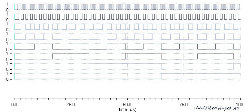
The simulation in Cadence results:

The wave diagram of the vector signal:


can share how to run this code on cadence.
Hi ChakriPyla,
This should be part of another tutorial. I take note for future posts.
Thanks for the feedback
Regards
Alberto