How to write an ideal comparator in Cadence with vhdlams HDL language? The comparator checks if the actual input voltage pin is above the reference voltage or not.

The block functionality is quite simple: it compares 2 analogue input voltages (Vin and Vref) and outputs a digital signal (result) with the comparison result.
It returns a digital HIGH when Vin is greater than the reference voltage Vref
This is a Mixed-Signal block, why?
- The inputs are analog
- The output is a digital std_logic signal named “result”.
Vhdl-ams code
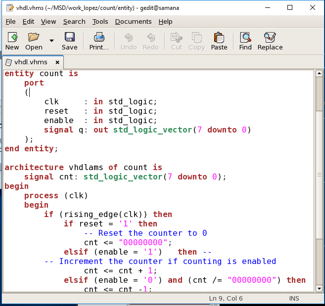
The full code must be inserted as a new view:
library ieee, std;
use ieee.std_logic_1164.all;
use ieee.electrical_systems.all;

entity comparator is
    GENERIC(
        Vthres : REAL := 0.1  --threshold
    );
    PORT(
        TERMINAL Vin : ELECTRICAL;
        TERMINAL Vref : ELECTRICAL;
        result : out std_logic
    );
end entity comparator;

ARCHITECTURE vhdlams of comparator IS
      QUANTITY Volt ACROSS Vin TO Vref;
BEGIN
    --result <= '1' when (Vin > Vref) else '0'; --without threshold
    result <= '1' when Volt'above(Vthres) else '0'; --With threshold
END vhdlams;
Test bench
A small test bench was set to prove the functionality of the mixed-signal block.
It was built with two ideal voltage sources as stimuli to simulate the two input voltages.
In this case, Vref = 2.5V and Vin = 18sin(5000000·t)

The wave diagram of the simulation verifies the functionality:


Hi Alberto,
Great content.
Can you help me if we need to have a clock based comparator ?
Regards,
Rohith
Hello,
For the clock based comparator (also know as latched comparator) you must cut the current of the comparator activating only the current source of the comparator during the high clock signal (or low).
You can find more in google if you search about “clocked comparator” or latched comparator”
Best Regards
Alberto