A model of the solar cell is built in Verilog-ams. This is needed in order to perform the simulation of the MPPT in a Solar Energy Harvester.

A ideal voltage source, for example from analogLib in Cadence, can deliver infinite power. In that case, the more voltage, the more current is provided by the cell and therefore more power is given. It would be not necessary a MPPT, in that particular , because the maximum power point (MPP) is located at the maximum voltage point.
A regular solar cell can, obviously, only supply a limited power. This maximum power point is not placed at the maximum operating voltage on the V-I graph. Usually, in monocrystalline solar cells, it is circa 70-80% of the open circuit voltage.
Three different solar cells were bought and tested in the lab under several light conditions. Later, a model was built approximating the characteristic curve of the real photo-cell.
The I-V curves of the model were made using the arc-tangent function, which is a built-in mathematical function in Verilog-ams.

The model provides different power curves in function of the available light. This is modelled by a generic parameter named light, which can be changed from the schematic via a design variable. Six intensity levels were implemented, numbered from 1 to 6, where 1 is the highest power curve corresponding to a mid-day light and number 6 is the light at sunset. The comparison between the model and real measurements can be found in the graphs below.
An active-high enable is also included in the model. The full Verilog-ams code of the solar cell model can be found here:
/////////////////////////////////////////////////////////////////////////////
//
// Engineer: Alberto Lopez
//
// Description: Verilog model of the solar cell IXYS
//
// Change history: 1/7/2018
//
/////////////////////////////////////////////////////////////////////////////
`include "constants.vams"
`include "disciplines.vams"
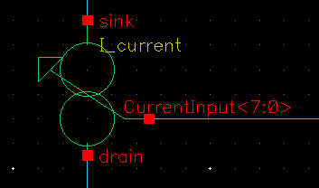
module SolarCell( EN, Vsolar, GND);
input EN;
electrical EN;
output Vsolar;
electrical Vsolar;
output GND;
electrical GND;
parameter real vdd = 1.2;
parameter real vthreshold = 0.6;
parameter real fc = 10M;
parameter real light = 6;
//Curve parameters
real gm;
real A;
real factor;
real Vop;
real vcp;
integer light_i;
integer en;
analog begin
@(initial_step) begin
en = 0;
A = 1;
Vop = 1;
factor = 10;
end
//Enable digitalization
@(cross(V(EN)-vthreshold,1)) begin
if(V(EN)>=vthreshold) en = 1;
else en = 0;
end
case(light):
0: begin A = 0; Vop = 0; end
1: begin A = -1.2; Vop = 1.71; end
2: begin A = -0.8; Vop = 1.64; end
3: begin A = -0.4; Vop = 1.50; end
4: begin A = 0.1; Vop = 1.43; end
5: begin A = 0.7; Vop = 1.36; end
6: begin A = 1.1; Vop = 1.22; end
default: begin A = -1.2; Vop = 1.71; end
endcase
//gm = A + atan(factor*(Vop-V(Vsolar))); //Transconductance
vcp=laplace_nd(V(Vsolar,GND),{1},{1,1/(6.28*fc)});
I(Vsolar,GND) <+ (A + atan(factor*(vcp -Vop)))/1000;
end //analog
endmoduleThe output of the previous model making a sweep for each light condition is the following:


Verilog-ams code of the solar cell model is not working in cadence. I got compilation warning and error. How can I resolve it
Hello Abhishek,
I dont know which king of error you are having, but probably the “escaped” symbols “greater than” and “less than” > <. Check them!
Regards
Alberto
the solar cell have three pin ,how i give the input and output ?
The 3 pins are, input, output and GND.
Actually there are 2 pins for the input and 2 pins for the output, but the GND is common, so you can use 3 for that.
Best Regards
Alberto