How to set up a video processing project with Vivado and the board Zybo, using the FPGA and programming it with VHDL.
In this project, I will explain how to create a starting project for video processing using the FPGA and VHDL language in Vivado.
This is a continuation of the post: “Video Processing with Zybo using the FPGA (I)“, where I explain a bit the basics and background of this project.
Contents
- Step 1: Create a New Vivado Project
- Step 2: Create a Block Diagram With Basic
- Step 3: Insert a VHDL Resource
- Step 4: Add Additional Onboard Perifericals Like Leds, Buttons or Sliders (optional)
- Step 5: Now You Can Insert Your VHDL Code on the Application Block
- Step 6: Create a Wrap
- Step 7: Synthesis, Implementation and Bitstream Generation
- Step 8: Export Hardware and Launch SDK
- Step 9: Create a New Board Support Package and a New Application
- Step 10: Program FPGA and Run the Hello World Code
Step 1: Create a New Vivado Project
After opening Vivado, first you need to create a new project on your workspace you want to work in.
Later name your project and choose the project location.
Choose Zybo as a target board or another Zynq board you want to use.
Step 2: Create a Block Diagram With Basic
Add a new Zynq_Processing_system diagram. Clicking on the block properties you can delete the AXI GPO interface and set the clock output of the PS to 200 MHz.
Also add the IPs from Digilent Dvi2rgb and rgb2vga and connect them like the last picture
Resuming: The block diagram shown in the Picture was made to interconnect different modules. The following main IPs were inserted
- Dvi2rgb: It converts the HDMI input into RGB raw video. From Digilent library.
- Rgb2vga: it converts the raw video into VGA output. From Digilent library.
- Processing_system7: This is an special block, that contains the configuration of the processing system of the Zynq. In this case only the clock output signal will be used from the processing unit.
- VideoProcessing: A self-made VHDL block. Here the user-application code should be inserted and modified. (Explaination on the next step)
Additional to these blocks two constants are used to configure the HDMI port as a sink.
Step 3: Insert a VHDL Resource
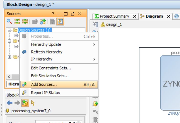
Now the user application block should be created, or imported. Therefore press ctrl+A or right click on the sources and select “add sources”.add a new source file.
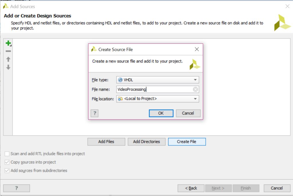
Create a new file with VHDL with some name, for example VideoProcessing.
Here Vivado ask you to insert the input and output of your block. This can be defined later, but it is good to create at least one input in order to Vivado recognize it as a block and let you instanciate without modifying. The inputs and outputs can be always modified later on the VHDL file.
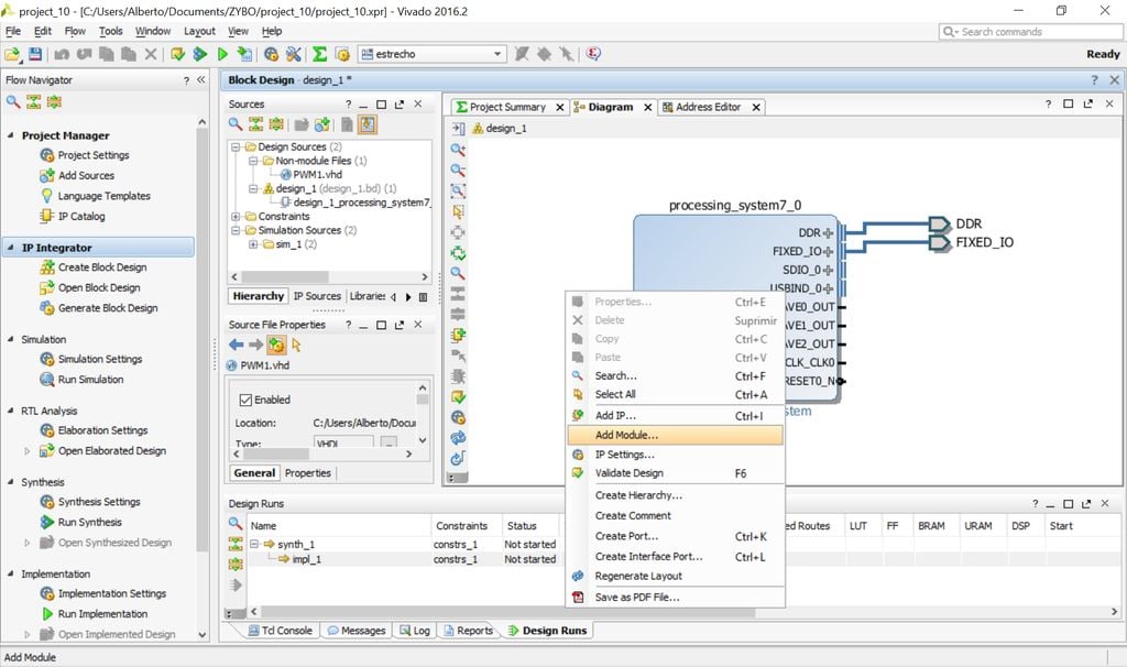
After that the new module can be on the block diagram instanciated. Right click on the empty diagram and select “add Module…”
One the module is instanciated, pressing the key F7 you can edit the VDHL code.
Step 4: Add Additional Onboard Perifericals Like Leds, Buttons or Sliders (optional)
To include some complementary options the sliders, buttons and leds are routed to the application block. The new block diagram should look like the picture.
Step 5: Now You Can Insert Your VHDL Code on the Application Block
Once added the VideoProcessing module, pressing F7 (or searching it on the sources) you can edit the code. An example of a minimal code can be found on the attached module.
----------------------------------------------------------------------------------
-- Company: MisCircuitos.com - Austria
-- Engineer: Alberto Lopez
--
-- Create Date: 07.04.2017 17:53:51
-- Module Name: VideoProcessing - Behavioral
-- Target Devices: ZYBO or Zynq boards
----------------------------------------------------------------------------------
library IEEE;
use IEEE.STD_LOGIC_1164.ALL;

entity VideoProcessing is
Port ( vid_data : in STD_LOGIC_VECTOR (23 downto 0);
pHSync : in STD_LOGIC;
pVSync : in STD_LOGIC;
pVDE : in STD_LOGIC;
clk_pix: in STD_LOGIC;
sliders: in STD_LOGIC_VECTOR(3 downto 0);
buttons: in STD_LOGIC_VECTOR(3 downto 0);
OUT_vid_data : out STD_LOGIC_VECTOR (23 downto 0);
OUT_pHSync : out STD_LOGIC;
OUT_pVSync : out STD_LOGIC;
OUT_pVDE : out STD_LOGIC;
OUT_clk_pix: out STD_LOGIC;
leds: out STD_LOGIC_VECTOR(3 downto 0)
);
end VideoProcessing;

architecture Behavioral of VideoProcessing is

begin

--video signals
OUT_vid_data(23 downto 16) <= vid_data(7 downto 0);
OUT_vid_data(15 downto 8) <= vid_data(23 downto 16);
OUT_vid_data(7 downto 0) <= vid_data(15 downto 8);

--Synchronization signals simply overdrive
OUT_pHSync <= pHSync;
OUT_pVSync <= pVSync;
OUT_pVDE <= pVDE;

end Behavioral;
Download the full code here: VHDL-minimal-code
Step 6: Create a Wrap
Create a new wrap before synthetise the block diagram.
Step 7: Synthesis, Implementation and Bitstream Generation
Add the constraints file attached.
Now you can run the synthesis and when it finalices without errors, you can open the synthetized design and check if all the pins are connected right, specially if you named the output pins differently.
Then run the implementation and after that generate the bitstream.
##Basic configuration for video processing application
## for ZYBO board using the HDMI as a sink and the VGA
## as an source
## Alberto L. Gasso

##IO_L5P_T0_AD9P_35
set_property PACKAGE_PIN E18 [get_ports hdmi_hpd[0]]
set_property IOSTANDARD LVCMOS33 [get_ports hdmi_hpd[0]]

##IO_L6N_T0_VREF_35
set_property PACKAGE_PIN F17 [get_ports {hdmi_out_en[0]}]
set_property IOSTANDARD LVCMOS33 [get_ports {hdmi_out_en[0]}]

##HDMI Signals
##IO_L13N_T2_MRCC_35
set_property PACKAGE_PIN H17 [get_ports hdmi_clk_n]
set_property IOSTANDARD TMDS_33 [get_ports hdmi_clk_n]

##IO_L13P_T2_MRCC_35
set_property PACKAGE_PIN H16 [get_ports hdmi_clk_p]
set_property IOSTANDARD TMDS_33 [get_ports hdmi_clk_p]
create_clock -add -name hdmi_clk_pin -period 13.00 -waveform {0 6.5} [get_ports hdmi_clk_p]

##IO_L4N_T0_35
set_property PACKAGE_PIN D20 [get_ports {hdmi_d_n[0]}]
set_property IOSTANDARD TMDS_33 [get_ports {hdmi_d_n[0]}]

##IO_L4P_T0_35
set_property PACKAGE_PIN D19 [get_ports {hdmi_d_p[0]}]
set_property IOSTANDARD TMDS_33 [get_ports {hdmi_d_p[0]}]

##IO_L1N_T0_AD0N_35
set_property PACKAGE_PIN B20 [get_ports {hdmi_d_n[1]}]
set_property IOSTANDARD TMDS_33 [get_ports {hdmi_d_n[1]}]

##IO_L1P_T0_AD0P_35
set_property PACKAGE_PIN C20 [get_ports {hdmi_d_p[1]}]
set_property IOSTANDARD TMDS_33 [get_ports {hdmi_d_p[1]}]

##IO_L2N_T0_AD8N_35
set_property PACKAGE_PIN A20 [get_ports {hdmi_d_n[2]}]
set_property IOSTANDARD TMDS_33 [get_ports {hdmi_d_n[2]}]

##IO_L2P_T0_AD8P_35
set_property PACKAGE_PIN B19 [get_ports {hdmi_d_p[2]}]
set_property IOSTANDARD TMDS_33 [get_ports {hdmi_d_p[2]}]

##IO_L5N_T0_AD9N_35
#set_property PACKAGE_PIN E19 [get_ports hdmi_cec]
#set_property IOSTANDARD LVCMOS33 [get_ports hdmi_cec]

##IO_L5P_T0_AD9P_35
set_property PACKAGE_PIN E18 [get_ports hdmi_hpd]
set_property IOSTANDARD LVCMOS33 [get_ports hdmi_hpd]

##IO_L6N_T0_VREF_35
set_property PACKAGE_PIN F17 [get_ports hdmi_out_en]
set_property IOSTANDARD LVCMOS33 [get_ports hdmi_out_en]

##IO_L16P_T2_35
set_property PACKAGE_PIN G17 [get_ports hdmi_in_ddc_scl_io]
set_property IOSTANDARD LVCMOS33 [get_ports hdmi_in_ddc_scl_io]

##IO_L16N_T2_35
set_property PACKAGE_PIN G18 [get_ports hdmi_in_ddc_sda_io]
set_property IOSTANDARD LVCMOS33 [get_ports hdmi_in_ddc_sda_io]

##VGA Connector
##IO_L7P_T1_AD2P_35
set_property PACKAGE_PIN M19 [get_ports {vga_r[0]}]
set_property IOSTANDARD LVCMOS33 [get_ports {vga_r[0]}]

##IO_L9N_T1_DQS_AD3N_35
set_property PACKAGE_PIN L20 [get_ports {vga_r[1]}]
set_property IOSTANDARD LVCMOS33 [get_ports {vga_r[1]}]

##IO_L17P_T2_AD5P_35
set_property PACKAGE_PIN J20 [get_ports {vga_r[2]}]
set_property IOSTANDARD LVCMOS33 [get_ports {vga_r[2]}]

##IO_L18N_T2_AD13N_35
set_property PACKAGE_PIN G20 [get_ports {vga_r[3]}]
set_property IOSTANDARD LVCMOS33 [get_ports {vga_r[3]}]

##IO_L15P_T2_DQS_AD12P_35
set_property PACKAGE_PIN F19 [get_ports {vga_r[4]}]
set_property IOSTANDARD LVCMOS33 [get_ports {vga_r[4]}]

##IO_L14N_T2_AD4N_SRCC_35
set_property PACKAGE_PIN H18 [get_ports {vga_g[0]}]
set_property IOSTANDARD LVCMOS33 [get_ports {vga_g[0]}]

##IO_L14P_T2_SRCC_34
set_property PACKAGE_PIN N20 [get_ports {vga_g[1]}]
set_property IOSTANDARD LVCMOS33 [get_ports {vga_g[1]}]

##IO_L9P_T1_DQS_AD3P_35
set_property PACKAGE_PIN L19 [get_ports {vga_g[2]}]
set_property IOSTANDARD LVCMOS33 [get_ports {vga_g[2]}]

##IO_L10N_T1_AD11N_35
set_property PACKAGE_PIN J19 [get_ports {vga_g[3]}]
set_property IOSTANDARD LVCMOS33 [get_ports {vga_g[3]}]

##IO_L17N_T2_AD5N_35
set_property PACKAGE_PIN H20 [get_ports {vga_g[4]}]
set_property IOSTANDARD LVCMOS33 [get_ports {vga_g[4]}]

##IO_L15N_T2_DQS_AD12N_35
set_property PACKAGE_PIN F20 [get_ports {vga_g[5]}]
set_property IOSTANDARD LVCMOS33 [get_ports {vga_g[5]}]

##IO_L14N_T2_SRCC_34
set_property PACKAGE_PIN P20 [get_ports {vga_b[0]}]
set_property IOSTANDARD LVCMOS33 [get_ports {vga_b[0]}]

##IO_L7N_T1_AD2N_35
set_property PACKAGE_PIN M20 [get_ports {vga_b[1]}]
set_property IOSTANDARD LVCMOS33 [get_ports {vga_b[1]}]

##IO_L10P_T1_AD11P_35
set_property PACKAGE_PIN K19 [get_ports {vga_b[2]}]
set_property IOSTANDARD LVCMOS33 [get_ports {vga_b[2]}]

##IO_L14P_T2_AD4P_SRCC_35
set_property PACKAGE_PIN J18 [get_ports {vga_b[3]}]
set_property IOSTANDARD LVCMOS33 [get_ports {vga_b[3]}]

##IO_L18P_T2_AD13P_35
set_property PACKAGE_PIN G19 [get_ports {vga_b[4]}]
set_property IOSTANDARD LVCMOS33 [get_ports {vga_b[4]}]

##IO_L13N_T2_MRCC_34
set_property PACKAGE_PIN P19 [get_ports vga_hs]
set_property IOSTANDARD LVCMOS33 [get_ports vga_hs]

##IO_0_34
set_property PACKAGE_PIN R19 [get_ports vga_vs]
set_property IOSTANDARD LVCMOS33 [get_ports vga_vs]

##Additional In-output pins
##On board leds
set_property PACKAGE_PIN M14 [get_ports {leds[0]}]
set_property PACKAGE_PIN M15 [get_ports {leds[1]}]
set_property PACKAGE_PIN G14 [get_ports {leds[2]}]
set_property PACKAGE_PIN D18 [get_ports {leds[3]}]

set_property IOSTANDARD LVCMOS33 [get_ports {leds[3]}]
set_property IOSTANDARD LVCMOS33 [get_ports {leds[2]}]
set_property IOSTANDARD LVCMOS33 [get_ports {leds[1]}]
set_property IOSTANDARD LVCMOS33 [get_ports {leds[0]}]

##On board sliders
set_property PACKAGE_PIN G15 [get_ports {sliders[0]}]
set_property PACKAGE_PIN P15 [get_ports {sliders[1]}]
set_property PACKAGE_PIN W13 [get_ports {sliders[2]}]
set_property PACKAGE_PIN T16 [get_ports {sliders[3]}]

set_property IOSTANDARD LVCMOS33 [get_ports {sliders[3]}]
set_property IOSTANDARD LVCMOS33 [get_ports {sliders[2]}]
set_property IOSTANDARD LVCMOS33 [get_ports {sliders[1]}]
set_property IOSTANDARD LVCMOS33 [get_ports {sliders[0]}]

##on board buttons
set_property PACKAGE_PIN R18 [get_ports {buttons[0]}]
set_property PACKAGE_PIN P16 [get_ports {buttons[1]}]
set_property PACKAGE_PIN V16 [get_ports {buttons[2]}]
set_property PACKAGE_PIN Y16 [get_ports {buttons[3]}]

set_property IOSTANDARD LVCMOS33 [get_ports {buttons[3]}]
set_property IOSTANDARD LVCMOS33 [get_ports {buttons[2]}]
set_property IOSTANDARD LVCMOS33 [get_ports {buttons[1]}]
set_property IOSTANDARD LVCMOS33 [get_ports {buttons[0]}]
Download the pin descriptions file: pin_descriptions.xdc
Step 8: Export Hardware and Launch SDK
Export the Hardware as shown in the pictures and launch SDK.
Step 9: Create a New Board Support Package and a New Application


Now create a board support package as the pictures show.
After that make a new application as a hello word template.
Program the FPGA and run (or debug) the “hello word example”
Step 10: Program FPGA and Run the Hello World Code

httpv://www.youtube.com/watch?v=s6YoaqllQ4U
In this small example, the colour channels are exchanged. Now the blue input is green and so on.
If problems let me know and see what we can improve.


Hi Alberto,
This is really informative. Thank you!
I have compiled everything and connected the camera to zybo (hdmi input), and output (vga) to a monitor screen.
But it’s not able to project to the screen. The camera display becomes blank, i assume it is connected to the monitor, but the monitor remain blank
Do we need a “C code” in the sdk? Or is the default hello world code sufficient?
Thanks for your help
Hello kit,
Are you sure that you are streaming from your camera? you can test it on another monitor…
I didn’t use any c code for the microprocesor. Yes with the simple hello world should be sufficient.
Best Regards
Alberto
Hi there,
I’m using your project as a starting point for my final project in my embedded systems class,however i keep getting an error that says that “TMDS” has not port map interface. I’m not sure how to go about fixing this. Any advice would be awesome, I’m also using the 2019.1 vivado.
Hello Carlos,
mmm… Sorry I don’t know about this TMDS error, and neither without the context. Are you using the Zybo board??
I invite you back if you fix the error to tell us the meaning!
Best Regards!
Alberto
Where is the hello world example code and could you make a github with the code and examples that you used for this project? It would be so much help as I don’t even really understand where to start for coding this myself. Thank you very much
Hello, the useful codes I used for his project are already online on this website! I hope it could help you 🙂
Hi Sir,
I’m able to passthrough the video data from hdmi to vga in vivado 2018.3, but without the VideoProcessing block.
I did little change in xdc file
#IO_L16P_T2_35
set_property PACKAGE_PIN G17 [get_ports DDC_scl_io]
set_property IOSTANDARD LVCMOS33 [get_ports DDC_scl_io]
#IO_L16N_T2_35
set_property PACKAGE_PIN G18 [get_ports DDC_sda_io]
set_property IOSTANDARD LVCMOS33 [get_ports DDC_sda_io]
and change the hdmi_in_ddc output pin to DDC. then run as per instructed.
However, when I put VideoProcessing block inbetween dvi2rgb and rgb2vga, no output video displayed on vga monitor. I’m still looking to the root problem and I suspect its because of clock in xdc file.
create_clock -add -name hdmi_clk_pin -period 13.00 -waveform {0 6.5} [get_ports hdmi_clk_p]
but I still not sure. can u help me?
Thank you so much! I’m currently learning VHDL with the Zybo-Board so I am very greatful for this.
Hello i’m learning EE from South Korea. first thanks for this valuable content. If input cam is “Raspberry Pi”, it works by Zybo board? Thanks.
The algorithm should be the same… but you may change the input source. Sorry, but I’ve never connect such camera to Zybo 🙁
Regards
Alberto
Hi Alberto,
Thanks for the useful content.
Can you explain, hopefully with a picture, how to set the clock output of the PS to 200 MHz? I’m using Vivado 2023.1 and not sure which clock are you referring to.
Thanks
Hi Sohail,
I dont have access to Vivado anymore, so I cant send you the picture, but you would find lots of info online.
Alberto