In drones the RC transmitter is a fundamental part of the system.
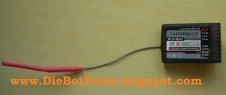
In this article, I will show how to use coded PPM RC signal. In this example, I am using the Turnigy 9XBC RC receiver.

Why do we want to use PPM RC signals?
The main reason is to spare pins of the main controller. Also, to reduce the number of cables considerably. For the case of aerial vehicles, weight is a critical factor and reduce the number of wires is one optimization to enlarge the flight time.
Differences between reading Servo signals or PPM signals:
The advantage of the PPM (Pulse Position Modulation) is that you can collect all the radio channel within one input. In that way, you can read all the channels with only one Arduino’s pin.
Less wires = less problems.
The idea is to read all radio channels within an interrupt routine of Arduino. Another workaround is to use a dedicated microcontroller and send the processed data to the main Arduino board by SPI or i2C.
Besides, if we disassemble the receiver housing and all input pins, we lose almost 70% weight and also save space. Very useful for drones.
PPM and PWM are two different protocols for radio information.
PPM has the advantage that you can get all the channels information through one port only. Some call it “PPM sum”, since it’s the sum of all channels. That helps a lot when you have limited number of connectors to your flight controller.
So, the drone has a PPM receiver. The receiver talks with my flight controller (the ArduPilot) over 1 single coded line. Then the flight controller will send PWM outputs to the ESCs and the servos for the camera mount of my drone.
By using the PPM input, I can embed now 10 PWM outputs from my Open Pilot Copter Control instead of 6 PWM outputs. That is for obvious reasons essential for me, because my camera mount needs 2 servo outputs plus the 6 ESC outputs for the hexacopter.
RC transmitters often have two operating modes: PPM (Pulse Position Modulation) and PCM (Pulse Code Modulation).
To receive correct signals from the radio, the RC transmitter must be set to PPM and ACRO mode, without TRIM, without DUAL-RATE and neither EXPONENTIAL. By this configuration, we avoid to distort the values sent by the transmitter software and by transmitting raw values.

With the Turnigy 9X 8C V2 does not have a PPM output and also you can not extract the PPM signal anywhere from the PCB. The reason is that the receiver works with two microprocessor: a receiver and a decoder. They talk by SPI between them. Another hardware solution is to add an extra chip to decode the SPI signal.
Here you can check a big list with a lot of common receiver and how to get the PPM signal. LIST

PPM Signal Detection
If you don’t know where is your PPM signal, you can upload this Jordi’s code to try to find the right pin in our receiver board. With one wire connected to pin 3, start touching every pins and spots of your receiver until you see random values on the Arduino Serial Monitor between 300 to 9000. That means you found it. Don’t forget connect ground to ground.
void setup()
{
Serial.begin(57600);
pinMode(3, INPUT);
}
void loop()
{
Serial.println(pulseIn(3, LOW));
}
#define channumber 6 //How many channels have your radio?
int channel[channumber]; //read Channel values
int PPMin = 4;

void setup()
{
  Serial.begin(9600); //Start serial
  pinMode(PPMin, INPUT); // Pin 4 as input
}

void loop()
{
  //waits ultil synchronize arrives > 4 miliseconds
  if(pulseIn(PPMin , HIGH) > 4000) //If pulse > 4 miliseconds, continues
  {
    for(int i = 1; i <= channumber; i++) //Read the pulses of the remainig channels
    {
 channel[i-1]=pulseIn(PPMin, HIGH);
    }
    for(int i = 1; i <= channumber; i++) //Prints all the values readed
    {
 Serial.print("CH"); //Channel
 Serial.print(i); //Channel number
 Serial.print(": ");
 Serial.println(channel[i-1]); //Print the value
    }
    delay(200);//Give time to print values.
  }
}
PPM reader with glitch filter:
#define channumber 6 //How many channels have your radio???
#define filter 10 // Glitch Filter
int channel[channumber]; //read Channel values
int lastReadChannel[channumber]; //Last  values readed
int conta=0; //couter


void setup()
{
  Serial.begin(9600); //Serial Begin
  pinMode(4, INPUT); //Pin 4 as input
  pinMode(13, OUTPUT); // Led pin 13
}

void loop()
{

  if(pulseIn(4, HIGH) > 3000) //If pulse > 3000 useconds, continues
  {
    for(int i = 0; i <= channumber-1; i++) //Read the pulses of the channels
    {
 channel[i]=pulseIn(4, HIGH);
    }
    for(int i = 0; i <= channumber-1; i++) //Average the pulses     { if((channel[i] > 2000) || (channel[i] <100))//If channel > max range, chage the value to the last pulse
 {
  channel[i]= lastReadChannel[i];
 }
 else
 {
 channel[i]=(lastReadChannel[i]+channel[i])/2; //Average the last pulse eith the current pulse
 conta++; //increment counter
 }
    }

    }
    if(conta > filter)//If counter is > than filter, then prints values
    {
 for(int i = 0; i <= channumber-1; i++) //Cycle to print values
 {
   Serial.print("CH"); //Channel
   Serial.print(i+1); //Channel number
   Serial.print(": ");
   Serial.println(channel[i]);
   lastReadChannel[i]=channel[i];
 }
 if(channel[4] > 1000) //If channel 5 is > than 500 turn on the led
 {
   digitalWrite(13, HIGH);
 }
 else
 {
   digitalWrite(13, LOW);//If not turn it off
 }
 delay(400); //Delay
 conta=0;//Restart counter.
    }
  }


Perdon por la ignorancia, pero tengo el mismo receptor que tenes vos, entiendo que no puedo leer el PPM, pero podre leer el pwm canal por canal?
was wondering how to go about connecting a spektrum 6ch receiver to my arduino, and then have my arduino output the signal like a trainer port would on a dx6i, reason i ask is i have a basic 4ch spektrum remote that has no trainer output
Hi. I have just bought a remote and receiver, I am trying to use 4x DC motor with hacking the receiver. I tried each step except the hacking inside, firstly I tried to read a ppm from a pin (channel 1 ) but it gave me random numbers, it didnt change when I play with remote. I have K-8X receiver, can you help me a bit please? thanks a lot for this very explanatory description
Can anyone help me? I want to receive a ppm signal and use it like a normal button to start a methode.
Can anyone help me? I want to receive a ppm signal and use it like a normal button to start a methode.
Decoding is the reverse of encoding. In decoding, it makes the information easier to understand.
Signals Decoding
Hey there! I’ve been following your website for a long time now and finally got the bravery to go ahead and give you a shout out from Atascocita Texas! Just wanted to tell you keep up the great job!
It is a pleassure. Thanks for your support 🙂
There is a bug in the first code example:
This: if(pulseIn(PPMin , HIGH) > 4000); //If pulse > 4 miliseconds, continues
Should be: if(pulseIn(PPMin , HIGH) > 4000) //If pulse > 4 miliseconds, continues
Note the ; char has been removed.
Yes, the semicolom after the if statement should be removed!
From now on the error is fix in the code 🙂
Thanks
Hi Alberto,
I have a flysky fsi6 I use with my arduino remote control snow blower.
I have connected a raspberry pi 4 to my arduino mega 2560 using the USB port for communication. Using the firmata protocol uploaded to the Arduino as slave and using the pi as master.
My question is :Would you happen to know how I can read RC channel inputs from the arduino on the raspberry pi 4 ? There is not very much info out there on the subject.