It has always been a bit intriguing and even confusing the nomenclature of these power supply voltages (Vdd and Vss) or (Vcc and Vee). But Why?
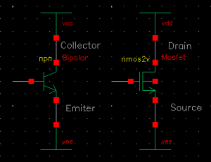
The following pictures are worth a thousand words…


Nowadays it is always used Vdd and Vss to refer to the positive and negative voltage respectively. Vdd is normally was used to be 5V but nowadays is 3.3V or even lower 1.8V or 1.2V. Vss is referred to be zero volts.
But when I learnt electronics in the high school and during my first years of electronics, that Vcc is the positive voltage (usually 5 volts) and Vee was the ground terminal. Later when we get to some circuits we find pins Vss and Vdd. Maybe many have not been intrigued by this but if you are reading this probably yes. So let’s continue:
What is the nomenclature?
This depends on the type of transistors that the electronic device has internally the microchip, circuit or microcontroller.
If internally formed by bipolar transistors (BJT), then the nomenclature is:
–Vcc for being the voltage applied to the Collector of the transistors
–Vee for being the voltage applied to the transistor Emitter leg
If internally built by Field Effect Transistors (FET, MOSFET), the nomenclature is:
–Vss for being the voltage applied to the transistor Source pin
–Vdd for being the voltage applied to the Drain of the transistors
So what is the polarity of each one?
Because NPN and NMOS transistors are used as a reference:
Vcc and Vdd are positive power voltages
Vee and Vss are Negative power voltages or are connected to ground.
Why the double letter?
Well, it is not really clear… let’s see some popular proposed explanations:
- It is derived from the binary notation system. In binary, a single digit represents a power of 2. Then, a double letter represents a higher power of 2 in terms of voltage. So, this would indicate higher power levels.
- The notation of doule “dd” or “ss” is to help to distinguish the power supply connections from other signal nodes in a circuit diagram, providing a clear indication of their purpose as voltage sources or voltage references. For example, between specific terminal of the transistors like Vds.
In a Nutshell…
This is a convention to refer to power supply voltages in electronics circuits has historical origins rather than a logic reason.
The Vdd and Vss notations have become widely recognized and accepted as standard in the industry for representations of power supply voltages in all the electronic circuits, regardless the technology is MOSFET or bipolar.
I hope this will be useful to you!


Thank you, Jesus blesses you
Extremely helpful post. Thank you.
Thanks a lot it was really helpful
Really that pictures worth a thousand words
Thank you, great explanation!
Really help! easy explanation
Here they will probably steal the books the first and then the booth…
Thanks you very much!!!
very well explained
Vcc stands for voltage (at) collector and is primarily used for bipolar devices, although I have seen it used with CMOS devices, probably out of convention. Vee stands for voltage (at) emitter and is usually the most negative.
Thank you!
Perfeito. Muito Obrigado. 👍👏
Best explanation I have come across
Ey, great explanation !!!!
awesome!
but why double b c and e? why not just vc vd and ve?
Thank you very much…this was really helpful.
So how do you measure the supply voltage in a microcontroller, by connecting to the VCC and VSS as ground?
Hello Mike, to measure the supply voltage you need a voltmeter and connect both terminal to VSS and VCC respectively
Best Regards
Alberto