How to know the region of operation of a single transistor in Cadence? What are the meaning of 0, 1, 2, 3 and 4 Regions in terms of cutt-off, saturation, sub-threshold, etc
The Virtuoso tool tells us valuable information about the operation region of any transistor in the circuit. For example, if a transistor is working in the saturation or in the triode region.
There is a standard operating point parameter named “region”. Although it depends on each specific technology, most of them are using it.
- 0 cut-off
- 1 triode / linear
- 2 saturation
- 3 subthreshold
- 4 breakdown
The condition for saturation region in based on the zeroth approximation:
|Vds|>=|Vds,sat|≈|Vgs-Vth|
What is the Meaning of the Operation Region?

The region parameter don’t tell you the complete information!!!
Historically, circuits were designed to operate in saturation (Strong Inversion) and what we want to bias our transistors in saturation all of the time. BUT in new designs, a new subthreshold circuit era is starting, sometimes circuits are biased to operate in the subthreshold region, using the weak inversion. Before, circuits were operating almost exclusively in saturation.
As low-voltage and low-power designs become more relevant, designers are starting to design circuits in Weak and Moderate Inversion.
The region parameter doesn’t give you the complete information if your device is working in Weak Inversion. You must take a look of Vds to see if you are in triode or saturation.

Vds and Vgs have completely 2 different roles:
- The Vgs parameter is determining the inversion level. How much inversion you have in the channel: Weak or Strong Inversion.
- The Vds parameter is determining the behaviour: Triode or Saturation. If the circuit is behaving as a Voltage-Controlled Resistor (VCR) in Triode or as a Voltage-Controlled Current Source (VCCS) in Saturation.
How to See the Operation Region in Cadence Virtuoso
The easiest way to annotate the DC operating points back in the schematic near each device is to right-click on the results window after a DC simulation and select Annotate>>DC operating points (as shown in the pic below).
The info shown in the annotations can be configured:
- First we annotate the DC operating points: right-click on the results of the DC sim >> Annotate >> DC Operating Points

After this, we will see the basic parameters of each transistor, by default Cadence shows the Vss, Id, Vgs and Vds. This changes which each technology how the symbols are defined.

To show the “region” parameter on the annotation, we must go to with right click to Annotations >> Setup.
Also you can go to the upper menu
View>> annotations>> Setup
Or you can make the changes on the menu:
View> DC annotation >Setup > select DC operating region > Display > region

In the annotation setup window, you can now choose between Component Parameter, DC operating point, Transient operating point or Model operating point. For me, the most common and useful options are:
- Component parameter refers to designer pre-defined parameters, such as width, length, etc. They can be useful to have in mind device parameters such as the geometry dimensions.
- DC operating point refers to the steady-state status, voltages and currents in a circuit. They are crucial to understand how your circuit behaves before applying any signal (transient or AC).
![]()
While the configuration, you can always click apply to preview the data annotations on the circuits.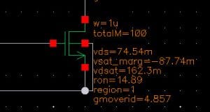
In my opinion, the most significative DC operating points data are “region”, “gmoverid”, “vsat_marg”, “vds”, “vgt” (= to overdrive), “vth” (at the begining) and “ron” (depending on the application).